Sunday 2 March 2014

CUCM Licensing Overview

To better understand the licensing of CUCM, lets start from the beginning.
CUCM was known as Selsius Call Manager before Cisco acquired it and re-christened it to Cisco Call Manager starting with Version 3.0. At that time, for CallManager 3.x and 4.x, we had to buy licenses with phones. There was no method to enforce licensing. A spare license was cheaper than original license and companies started to exploit this. CUCM was running on Windows server. Also, if we had CUCM software, we could install as many as nodes in a cluster as required.
From CallManager 5.x, it runs as an Appliance on a customized RHEL with a different shell. Cisco started the concept of DLUs. Each device required different number of DLUs depending on the device features. Each DLUs cost about 25$. Also introduced was the Node licensing. So installing a new subscriber required a license.
From CUCM 6.x, Cisco renamed CallManager to CUCM and introduces Feature license. You can't upgrade to any major version without feature license. You cannot start the CUCM service without a feature license. When upgrading between major versions, the DLU count would become negative and you need a feature license to get back to the original count.
CUCM 8.x onwards due to the large number of collaboration devies and licenses, Cisco introduced a new CUWL (Cisco Unified Workspace Licensing) {pronounced as COOL}. It consists of a license based on users rather than on devices i.e. if a user has access to only one device then you can get a basic license can scale upto 10 devices per user which is a professional license.
Here is a list of CUWL licenses made available:
Essential : 1 device/user (analog/Voice)
Basic : 1 device/user (Voice)
Enhanced : 1 device/user (Video)
Advanced : 2 devices/user (Video)
Standard : 2 devices/user (Video)
Premium : 4 devices/user (Video)
Professional : 10 devices/user (Video)
Also introduced was Cisco User Connect Licensing (UCL) provides user-based licensing for individual Cisco Unified Communication products. UCL is further broken down by device type for Communications Manager and is viewed as the replacement for the ‘DLU'.
Till 8.x, the licensing was done by Publisher. From 9.0, the licensing is done by ELM (Enterprise License Manager).
ELM is installed by default on every node. It can be installed as a standalone using CUCM OVA template and it can be used to license multiple servers.
- Abhinay Mylavarapu

Troubleshooting CUCM Database Replication

CUCM uses IBM Informix for database needs. We have no native access to this (unless you are a Cisco TAC Engineer who can gain temporary access to root).
If DB replication breaks, we see many symptoms in our IPT network like Phone registered to a Subscriber unable to make calls to phones registered on the other subscriber, unable to login to extension mobility etc.

We can make use on any one of these methods to check replication status:
  •  Open RTMT -- Click on : Call Manager --> Service --> Database Summary
  • Open a web browser, type in https://<IP address>:8443/cucreports/ , Enter your authorized username and password.
    Go to : Database Status Report
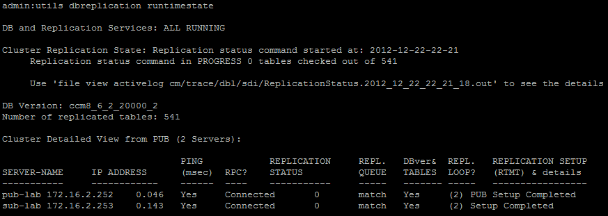
  • Using putty, SSH to the CUCM to take CLI access and run this command : utils dbreplication runtimestate --> REPl.LOOP? is the current state.

Here is what the replication state means :
0 - Initialization state : This state indicates that replication is in the process of trying to  setup. Being in this state for a period longer than an hour could  indicate a failure in setup.

1 - Number of replicates not correct : This state is rarely seen, can indicate its still in the setup process. Being in this state for a period longer than an hour could indicate a failure in setup.

2 - Replication is good : All is well in paradise :)

3 - Tables are suspect : Logical connections have been established but we are unsure if tables match. This can happen because the other servers are unsure if  there is an update to a user facing feature that has not been passed  from that sub to the other device in the cluster.

4 - Setup failed / Dropped : The server no longer has an active logical connection to receive  database table across. No replication is occurring in this state.

If State is other than 2, check:
  • Server & Cluster connectivity : Check TCP/UDP ports needed to be opened on the network. To get the port list for your CUCM version, just google : CUCM < your version> ports
  • Configuration files (if on older CUCM - extremely rare) :
  1. /etc/hosts ---> local resolution of hostnames to IP addresses
  2. /home/informix/.rhosts ---> hosts trusted to make database connections
  3. $INFORMIXDIR/etc/sqlhosts ---> full list of CCM servers for replication
  • Check if server times are correct and synced (NTP working fine)
  • DNS not configured properly (forward/reverse lookup)
  • NTP not reachable/time drift between server
  • A Cisco DB replicator service not running/not working
  • Cisco Database Layer monitor (DbMon) hung/stopped

Useful Commands :


  • utils dbreplication setrepltimeout -- The default value is set to 300 seconds. You can validate this by running "show tech repltimeout". This is the timer used to put multiple servers into one run of the data sync. In other words, it is the "batching" timer. This affects when the broadcast realize template and data sync will fire (n seconds from the end of the first defined server). Clustering over WAN (CoW) long delays can cause the data sync process to be exponentially longer. Try to sync the local servers first.
 
  • utils dbreplication repair -- in CUCM 5.x, this command meant a reset of the replication, whereas, in CUCM 6.x and higher versions, this means a repair of the data. It runs a repair process on all tables in the replication for all servers that are included in the command. Run this command when RTMT = 2, not when RTMT = 0 or 3.
 
  • utils dbreplication repairtable / repairreplicate -- This command essentially does the same thing as the repair command, but runs on only one table / replicate, hence making the process much faster. It fixes the out of sync data for that table / replicate. You can verify by running "utils dbreplication status" to see if there are any mismatches or errors found. It is particularly useful on large CUCM clusters. Run this command when RTMT = 2, not when RTMT = 0 or 3.
 
  • utils dbreplication stop -- You should only be running this if you want to stop replication setup. The only way to recover from a stop is with a reset. This command removes the set-up indicator file i.e. the dbmonpreflightcheck file and kills the currently running replication commands. It pauses for the duration of repltimeout timer, so if you run replication commands soon after running a stop, it could kill the commands again. Run this command when RTMT = 0, not when RTMT = 3
 
  • utils dbreplication reset -- This command causes replication to be torn down and then set-up. You should run this command when RTMT = 4 or when you have issued stop. Successful completion of this process results in RTMT = 2.
 
  • utils dbreplication clusterreset -- Avoid running this command. It is for debugging replication set-up problems. It bypasses the RTMT settings, cluster requirements and normal CUCM set-up. It causes services to go out of sync with the database because it syncs data without change notification. The services need to be restarted when this command is run, no exceptions!
 
  • utils dbreplication dropadmindb -- Run this command when there is a looping attempt to define a server in replication. It's usually not the server that's failing, it's the pub which is corrupted as a result of an attempt or the sub, prior to the current one attempting set-up.
 
  • utils dbreplication forcedatasyncsub -- This command takes a backup of the publisher and restores it to the subscriber(s) and resets up replication. It requires a serivces restart on the subscriber so they get the new values.
 New Commands and Database Improvements in CUCM 9.x: 
  • Re-engineered CLI forcedatasyncsuball (Lightening fast) -- This command can now restore a larger cluster in a shorter period of time!

  • New CLI rebuild is a stop, drop and reset all in one (and faster) -- The architecture of Rebuild is multi-threaded, the total operation time is much shorter than executing three different CLI commands (stop / drop / reset). Rebuild, is a master command that will stop, delete and trigger the replication setup signal across the cluster automatically and in parallel:
  1. Stop DB Replication – stop the current replication setup process if exists
  1. Remove server from database – Remove replication from the network by either “cdr delete”, dropping the syscdr database or renaming the syscdr database remotely
  1. Trigger Dbmon on the subscriber to submit a replication setup request on to publisher.
 
  • New CLI utils replication status table/replicate -- The "utils dbreplication status" command is lengthy when it runs. If only one table is suspect, then you have to wait for all the tables to check. Being able to check one table speeds up checking of replication.

 
  • Better Log Collection -- "utils create report database" collects all the database logs in one go. Also, ercollect.sh script is embedded into the server for IBM root cause cases. The script is on the server now, no need to transfer and change permissions. It is accessible via root access only.
 
  • Faster and more accurate Runtimestate CLI -- This command is now multithreaded, making it much faster. The output will also be logged for historical RCA. If there are any unreachable servers in the cluster, this command will no longer hang. Some additional information will be included in it such as repltimeout and IDS server number.

- Abhinay Mylavarapu

Thursday 30 January 2014

IP Phone Boot Up and Registration

Hi Reader and welcome to this blog on IP Phone Boot up process and Registration. I will explain to you all the things involved in registering an IP Phone and go through the entire process in detail. So here goes...

The very first thing that happens after we connect an IP Phone to a switch-port is that it receives power from the port.. Now, there are two ways in which an IP Phone can receive power and those are:

Inline Power:
  • When the phone is connect to switch-port, the port sends FLPs (Fast Link Pulse) which are bursts of electric signal lasting 125 microseconds on the transmit pair.
  • The switch-port expects to receive this back on the receive port.
  • Devices that need power have a LPF (Low Pass Filter) between the transmit and receive pairs designed to pass only FLPs.
  • On receiving the FLP, power is applied
  • The port is taken out of discovery mode and put into ethernet auto-negotiate.
  • "Wait for Link" timer of 5 seconds starts. If the phone link is detected, power is kept on else power is switched off and port goes back to discovery mode.
Power over Ethernet:

(Industry standard - IEEE 802.3af delivers upto 15.4 Watts of power per port, using 48 volts)
  • When the phone is connected to switch-port, 2.7 V to 10 V is applied between the transmit and receive pairs.
  • Devices that need power have a 25K ohms resistance between the transmit and receive pairs.
  • If this is detected, then power is applied to the device if enough is available.
  • If we disconnect the phone from the port, the power connection is terminated in less than 250ms.

Note: The switch-port doesn't have a power ON mode to protect the NICs (Network Interface cards) which do not expect to receive power from the network.The switch queries its NMP (Network Management Processor) to determine whether enough power is available to power a device. Power can be sent through the cable on spare pairs or data pairs (phantom power). CDP is used for power negotiation after the link is up and phone has booted on. If switch doesn't support CDP, there is no reduction in power.
       Contact               Media Direct Interface Signal
   1                            Transmit +ve
            2                                   Transmit -ve
            3                                Receive +ve
            4                                  -ve
            5                                  -ve
            6                            Receive -ve
            7                                  +ve
8      +ve

Upon receiving power , the IP phone:
1) The phone obtains Voice VLAN information from the switch to which the IP phone is connected or uses statically defined Voice VLAN information [Admin VLAN ID]. Phone sends a maximum of 3 CDP messages requesting Voice VLAN ID. If it receives a response from switch with the VLAN, the packets are sent tagged, else the packets are untagged.

2) Requests DHCP information / uses statically configured settings. It provides the IP phone with the IP address of the TFTP server.
Settings > 3- Network Configuration > DHCP Enabled > YES -- AUTO
                                                                                         NO -- MANUAL

3)  Contacts TFTP server to download a configuration file - SEP<devicemac>.cnf.xml / SEPDefault.cnf.xml (if 1st one is not found)

These files contain :
    • List of three call managers plus an optional SRST router for IP phone to connect.
    • Load information specifying firmware version IP phone should be using.
    • URLs for directories, services, information and idle.
4) Phone reads load ID and version stamp and compares with current load.
If mismatched, loads new load from TFTP, IP phone resets and repeats entire boot process.

5) Phone attempts registration to its primary CUCM, If it is unavailable, IP phone tries the subsequent servers from the list provided via TFTP.

SKINNY CLIENT REGISTRATION :
- IP phone sets up a TCP connection with the CUCM
- IP phone sends a Alarm Message which contains Device name, load of the IP phone, Alarm status, Phone's IP address.
- IP phone sends a stationRegisterMessage containing Device name, Device type and IP.
- IP phone sends a StationIPPortMessage containing the TCP port on which it is listening.
- CUCM sends a StationRegisterAck to the IP phone to indicate successful registration.
- CUCM queries the IP phone about its capabilities to which the IP phone replies.
- IP phone requests for Softkey template, Button template, Softkey set, line status, speed-dial status and date and time.
- Apart from the above, CUCM sends the output prompt display message - Your Current Options.

I hope you understood the above and any doubts you can always comment here and I will help to solve them.

- Abhinay Mylavarapu.

Saturday 2 November 2013

Troubleshooting ISDN on Cisco Gateways

  • ISDN:
ISDN is a set of communication protocols that enables simultaneous transmission of voice, data, video and other network services over traditional networks like PSTN. The ISDN mainly relies on the following:
  
       Q.921 : Setup of D channel and ensure reliable delivery of Q.931 Signaling.
                    Also known as Link Access Protocol - D channel [LAPD]

       Q.931 : Call Signaling.

Let have a look at the output of a basic troubleshooting command. I have two different scenario outputs shown below. The command is : show isdn status

SCENARIO 1 :

Global ISDN Switchtype = primary-5ess
ISDN Serial1:23 interface
        dsl 1, interface ISDN Switchtype = primary-5ess
    Layer 1 Status:
        ACTIVE
    Layer 2 Status:
        TEI = 0, Ces = 1, SAPI = 0, State = TEI_ASSIGNED
    Layer 3 Status:
        0 Active Layer 3 Call(s)
    Activated dsl 1 CCBs = 0
    The Free Channel Mask:  0x807FFFFF
    Total Allocated ISDN CCBs = 5
The Layer 2 status "TEI_ASSIGNED" indicates that the D channel is not up. 

SCENARIO 2 :

Global ISDN Switchtype = primary-5ess
ISDN Serial0:23 interface
        dsl 0, interface ISDN Switchtype = primary-5ess
    Layer 1 Status:
        ACTIVE
    Layer 2 Status:
        TEI = 0, Ces = 1, SAPI = 0, State = MULTIPLE_FRAME_ESTABLISHED
    Layer 3 Status:
        5 Active Layer 3 Call(s)
    Activated dsl 0 CCBs = 5
        CCB:callid=7D5, sapi=0, ces=0, B-chan=9, calltype=DATA
        CCB:callid=7D6, sapi=0, ces=0, B-chan=10, calltype=DATA
        CCB:callid=7DA, sapi=0, ces=0, B-chan=11, calltype=DATA
        CCB:callid=7DE, sapi=0, ces=0, B-chan=1, calltype=DATA
        CCB:callid=7DF, sapi=0, ces=0, B-chan=2, calltype=DATA
    The Free Channel Mask:  0x807FF8FC

The Layer 2 status "MULTIPLE_FRAME_ESTABLISHED" indicates successful set up of 
D channel and the output also shows 5 active calls on Layer 3.

CCB = Call Control Blocks, appears in the message only when there are active calls..
 Displays the Call ID and B Channel it is occupying.

Layer 1 Status:
If not active, check physical layer connectivity.
Also check : show controllers [ t1 | e1 ]

Layer 2 Status:

  • TEI_ASSIGNED : D channel is not up.
1) Check switch-type and PRI timeslots.
2) Check network user side configuration. (On the Serial x:23 interface : NO SHUT, ENCAPSULATION, NO LOOPBACK)

Run the debug ISDN q.921 command.

The actual process of setting up of D channel consists of the following messages (in this case User is the gateway and network is the PSTN) :
UI : Unnumbered Information Frame

SAPI : Service Access Point Identifier. It is used to identify the type of frame by the value it carries.
           0 = Q.931
           63 = TEI Assignment
           16 = X.25

SABME : Set Asynchronous Balanced mode Extended

UA : Unnumbered Acknowledge

Router sends an SABME message and receives a UA frame to synchronize with the TELCO switch.

If the UA frame is received, the D Channel is UP.

When D channel is up, we receive Receive Ready packets (Keepalives) every 10 seconds :
ISDN Se0:23: RX <- RRp sapi=0 tei=0 nr=18

If 4 keepalives are missed, D channel is DOWN and setup begins again.

If instead of UA frame, we receive a BAD FRAME message, then there is a problem with the TELCO.

If we receive nothing, it may be a problem with the Hardwire Plug or the Router itself, contact CISCO TAC.


FOR A TROUBLESHOOTING FLOW CHART REFER :


-Abhinay Mylavarapu.

Friday 1 November 2013

CUCM Clustering and Database Replication

What is a CUCM Cluster?
- A CUCM Cluster is a group of CUCM servers running the same version of CUCM working together as a single system to provide high availability of services for clients, transparent sharing of resources, features and enables system scalability.
- When a failure occurs on one server in a cluster, resources are redirected and the workload is redistributed to another server.
- The clustering feature of CUCM also provides a mechanism for distributing call processing and database replication among multiple CUCM servers. - The CUCM can support these two types:

Cluster : 
  • Supports upto 30000 IP phones
  • Can be scaled to a maximum of 20 Servers in which there can be a maximum of : 1 Publisher, 8 Call Processing Subscribers, 2 TFTP servers, 9 Other Servers.
Supercluster (Mega Cluster) :
  • Requires Cisco BU approval via Cisco Accounts Team
  • Supports upto 60000 IP phones
  • Can be scaled to a maximum of 21 Servers in which there can be a maximum of  : 1 Publisher, 16 Call Processing Subscribers, 2 TFTP Servers, 2 Other servers
There are two types of data communication between CUCM servers :
1) Database Replication :
Replication is the process of copying and maintaining database objects in multiple databases that make up a distributed database system. Replication can improve the performance and protect the availability of applications because alternate data access options exist.
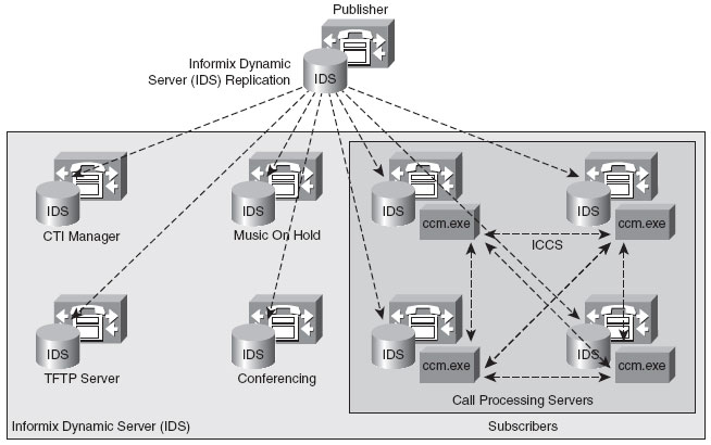
- Read/write copy of the database is with the Publisher.
- This database is located in the IBM-IDS server. (Informix Dynamic Server manufactured by IBM Corp.)
- This is replicated to all Subscribers in a Hub (Publisher) and Spoke (Subscriber) topology i.e in a single direction from the Publisher to all subscribers (as shown in above figure).
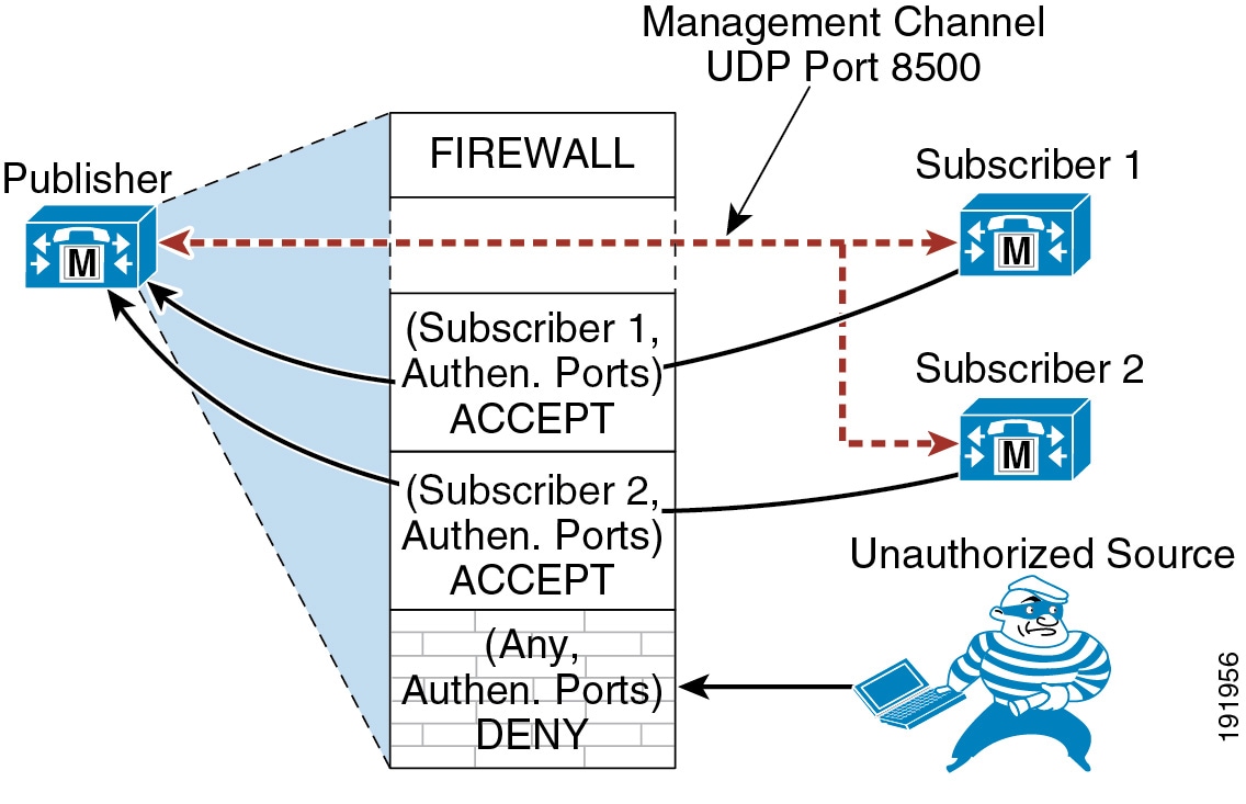
- The Database replication is secured using embedded Red Hat Linux, iptables dynamic firewall (within the CUCM) and database security password (given during installation)

2) Cluster Communication :
ICCS Signaling :
- Used to replicate run-time data such as : Registration of devices, Locations bandwidth, Shared Media Resources.
- This signaling runs only between the servers that have the "ccm.exe" service i.e the Call manager service running (Call Processing agents).
- Uses TCP ports 8002-8004.
CDR & CAR :
- Call Detail Records are logged by the Call Processing Engine taking the call.
- These are periodically pushed to the Publisher server.
- The Cisco CAR or any third party billing application server always points to and collects data from the Publisher.

User Facing Features :
These features are two way replicated between Publisher and Subscriber.
These features work even if the publisher is down (from 8.x) :
  • Call Forward All (CFA)
  • MWI
  • Privacy Enabled/Disabled
  • DND
  • Extension Mobility Login
  • Hunt group login
  • Device Mobility
  • CTI CAPF Status
  • Credential Authentication
- Abhinay Mylavarapu.

Sunday 1 September 2013

"Hello World"

Hello World! I've been wanting to start my blog for a while now but time and other constraints have been preventing me, but now I have broken all the shackles and here I am..! Yaaaaayyy!!! This is a STRICTLY NO NONSENSE take on Cisco Voice and Collaboration.

With this blog, I aim to share my experience, knowledge and my self-prepared notes related to Cisco Voice and Collaboration. I have decided to license this blog under Creative Commons Attribution-NonCommercial-ShareAlike 4.0 International License.. This means that you can take what I will write on this blog, reuse it for whatever you see fit, or combine it with other content under the same license provided you:
1) Quote where you got it from i.e me (Abhinay Mylavarapu) and this blog.
2) You share the result under the same license.
3) The content you use from here is ONLY for non-commercial uses.

Feel free to leave a comment / suggestion / feedback on my posts.

The images used in my blog are all courtesy of Cisco Official Documentation unless stated otherwise.

You can add me on
Facebook : Abhinay Mylavarapu
Google+ : Abhinay Mylavarapu